Ultrasonic Transducers
Boston Piezo-Optics is a major supplier of transducer crystals to transducer manufacturers. BPO does not manufacture complete ultrasonic transducers.
The ultrasonic transducer is an extremely important and critical part of any ultrasonic test. Selection of the proper transducer for a particular application is most important. Factors including instrument conditions and settings, material properties, and coupling conditions will also impact test results. Transducers can be selected for sensitivity or resolution. Sensitivity is defined as the ability of a transducer to detect small defects in materials. Resolution is the ability of a transducer to separate signals produced by two reflectors when they are close together either perpendicular to the beam or parallel to the beam. A transducer that is highly damped helps shorten the reflected pulse allowing the transducer to resolve closely spaced defects. Transducer device manufacturers can provide focused transducers for improved sensitivity and resolution, and a large selection of polarized ceramic compositions, single crystals, polymers and piezo-composite materials to vary the transducer performance.
The Ultrasonic Transducer
Sound that is generated above the level of human hearing range is called ultrasound. Although ultrasound typically starts at 20 KHz, most ultrasonic transducers start at 200 KHz. Ultrasound, which is similar in nature to audible sound, has far shorter wavelengths and is far more suitable to detect small flaws. These shorter wavelengths are what make ultrasound and ultrasonic transducers extremely useful for nondestructive testing and measurement of materials.
An ultrasonic transducer itself is a device that is capable of generating and receiving ultrasonic vibrations. An ultrasonic transducer is made up of an active element, a backing, and wearplate. The active element is a piezoelectric or single crystal material which converts electrical energy to ultrasonic energy. It will also then receives back ultrasonic energy and converts it to electrical energy. The electrical energy pulse is generated from an instrument such as a flaw detector.
The backing is most commonly a highly attenuative and very dense material and is used to control the vibration of the transducer crystal by absorbing the energy that radiates from the back face of the piezoelectric element. When the acoustic impedance of the backing material matches that of the piezoelectric crystal, the result is a highly damped transducer with excellent resolution. By varying the backing material in order to vary the difference in impedance between the backing and the piezoelectric crystal, a transducer will suffer somewhat and resolution may be much higher in signal amplitude or sensitivity.
The main purpose of the wearplate is simply to protect the piezoelectric transducer element from the environment. Wearplates are selected to generally protect against wear and corrosion. In an immersion-type transducer, the wearplate also serves as an acoustic transformer between the piezoelectric transducer element and water, wedge or delay line.
The Sound Field
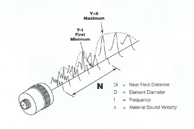
The sound field of a transducer has two distinct zones. These zones are called the near field, which is the region directly in front of the transducer, and the far field which is the area beyond "N" where the sound field pressure gradually drops to zero. Because of variations of the near field, it may be very difficult to accurately measure and evaluate flaws.
The near field distance is a function of the transducer frequency, element diameter, and the sound velocity of the test material as shown in the following equation:
N = D2/4c
The Sound Beam
There are several sound field parameters that are very useful in describing the characteristics of an ultrasonic transducer. Knowledge of the focal length, beam width and focal zone may be necessary in order to determine whether a particular transducer is appropriate for an application.
One reason that focusing increases the sensitivity of a transducer is that it results in a decrease in the sound beam diameter. This means that a small flaw will reflect a greater portion of the transmitted sound energy. The -6dB pulse-echo beam diameter at the focus can be calculated with the following equation:
BD (=6dB) = 1.028 Fc/fD
BD = Beam Diameter F = Focal Length
The starting and ending points of the focal zone are located where the on-axis pulse-echo signal amplitude drops to -6dB of the amplitude of the focal point. The length of the focal zone can be calculated with the following equation:
Fz = NS2F [2/(1 + .5SF)]
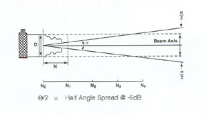
All transducers have beam spread and the consideration of the beam spread is important when inspecting flaws that may be close to certain geometric features of the material to be tested. These features include side walls and corners which may cause spurious echoes that could be mistaken for flaws or defects.
For flat transducers the -6dB pulse-echo beam spread angle is well defined and is given by equation:
Sin (α/2) = .514c/fD
It can be seen from this equation that beam spread in a transducer can be reduced by selecting a transducer with a higher frequency or a larger diameter, or both.
Transducer Types
Straight Beam Contact Transducers are the most common and frequently used to introduce longitudinal waves into a material. Also, by using special elements, normal incidence shear wave or a combination of longitudinal/shear wave transducers can be made. This type of transducer is used in direct contact with the test material and therefore requires a highly durable wearplate.
Angle Beam Transducers utilize the basic principle of refraction and mode conversion to produce refracted shear or longitudinal waves in the test material. The angle of incidence required to produce the desired refracted wave is calculated from Snell's Law.
The following formula may be used to calculate the Wedge angle (Q1) required to generate the desired mode and refracted angle (Q2) in the material under test.
Sin Ø1/Sin Ø2 = V1/V2
Ø1 = Wedge Angle
Ø2 = angle of refracted wave in test material
V1 = Longitudinal velocity of wedge material
V2 = Velocity of material being inspected for the desired mode
Dual Element Transducers use separate elements to transmit and receive ultrasound signals. The elements are typically cut at an angle and mounted on delay lines. This helps to improve near surface resolution and the cross-beam design also helps to create a focus which makes dual element transducers more sensitive to echoes from irregular defects caused from corrosion and pitting.
Immersion Transducers have several advantages over contact-type transducers. First, their uniform coupling reduces variations in sensitivity. Second, immersion transducers offer increased speed from the ability to perform automated scanning. Third, the focusing of immersion transducers increases the sensitivity to small defects. Immersion transducers are available in unfocused, spherically focused, and cylindrically focused configurations. An unfocused immersion transducer is used for general applications in the measurement of thick materials. A spherically focused transducer will improve the sensitivity to small flaws and defects. A cylindrically focused transducer is typically used in the measurement of tubing raw stock. The range of focal lengths for a spherical or cylindrical transducer is limited to the transducer's near field and is generally a maximum of 0.8N.
